Vortex Tube, Instant cooling, quick install, adjustable, compact refrigeration
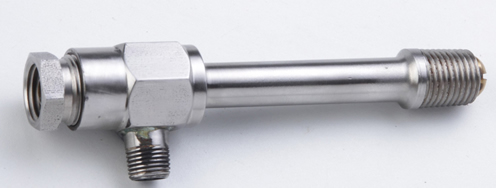
What is a Vortex Tube?
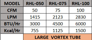
What is a General imsubs® Vortex Tube? The General imsubs® Vortex Tube is an effective, low cost solution to a wide variety of industrial spot cooling and process cooling needs. Compressed air is injected into the vortex tube, flows at a rate of up to 1,000,000 RPM towards the 'hot' end of the tube. Once this hot air reaches the end, a small amount is exhausted through a control valve. The rest of the air is forced backwards towards the other end and exits as 'cold' air. The Vortex Tube can decrease temperatures by ~115°F (46°C) and raise temperatures up by ~200°F (93°C) from the initial inlet air temperature. Vortex tubes are available in three sizes, Small, Medium and Large depending upon compressed air consumption.
Which Vortex Tube will best suite my needs?
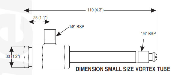
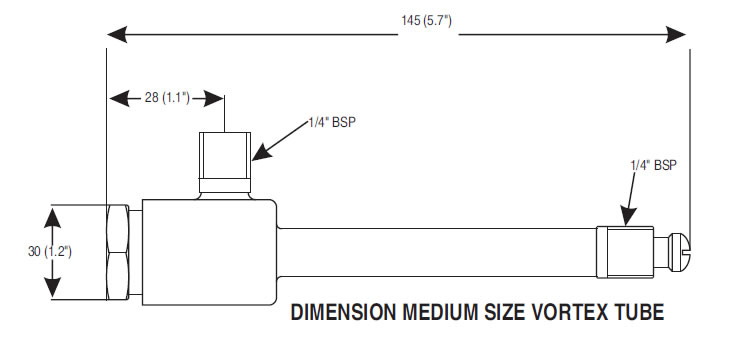
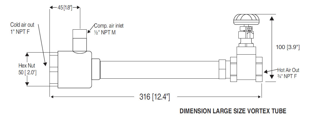
General imsubs® Vortex Tubes are available in 3 sizes (Small, Medium and Large). Each Vortex Tube is constructed of stainless steel. The wear resistance of stainless steel, as well as its resistance to corrosion and oxidation, assures that Vortex Tube will provide years of reliable, maintenance free-operation.
| Advantage of Vortex tube | ||||||||||||||||||||
|---|---|---|---|---|---|---|---|---|---|---|---|---|---|---|---|---|---|---|---|---|
 |
||||||||||||||||||||
|
||||||||||||||||||||
 |
||||||||||||||||||||
| Applications or Vortex Tube | ||||||||||||||||||||
 |
||||||||||||||||||||
|
||||||||||||||||||||


HOW VORTEX TUBES WORKS
- (A) Compressed air, normally 80 to 100 PSIG (5.5 - 6.9 BAR) enters the Vortex Tube through a standard BSP inlet and tangentially through a generator into the vortex spin chamber.
- (B) This air stream spinning at up to 1,000,000 RPM travels in one direction along the small (hot end) tube and then is forced back through the center of this outer vortex.
- (C) The brass control valve on the hot end allows for quick n' easy adjustment of the "cold fraction".
- (D) As the center column travels towards the opposite end, it gives off kinetic energy in the form of heat to the outside stream of air and exits the vortex tube as cold air.
PERFORMANCE: Performance mentioned here is at tube being set to maximum refrigeration. Air flow is at 7 bar (100 PSI) pressure.
7500 Series Vortex Tube Specifications
The 7500 series Vortex Tube is used in most industrial applications, such as electrical control panel cooling, tool cooling, and parts cooling. These Vortex Tubes optimize airflow and temperature drop to produce maximum cooling power.
| Size | Model No. | Air Consumption | BTU/Hr. @ 100 PSIG | Kcal/Hr. @ 6.9 BAR |
|---|---|---|---|---|
| Small | 7502 | 2 SCFM (57 SLPM) | 145 BTU/Hr. | 37 |
| Small | 7504 | 4 SCFM (113 SLPM) | 275 BTU/Hr. | 69 |
| Small | 7508 | 8 SCFM (227 SLPM) | 560 BTU/Hr. | 141 |
| Medium | 7510 | 10 SCFM (283 SLPM) | 700 BTU/Hr. | 176 |
| Medium | 7515 | 15 SCFM (425 SLPM) | 1100 BTU/Hr. | 277 |
| Medium | 7525 | 25 SCFM (708 SLPM) | 1800 BTU/Hr. | 454 |
| Medium | 7530 | 30 SCFM (850 SLPM) | 2060 BTU/Hr. | 519 |
| Medium | 7540 | 40 SCFM (1133 SLPM) | 2800 BTU/Hr. | 706 |
7700 Series Vortex Tube Specifications
The 7700 series Vortex Tube is used in applications that require extreme cold temperatures, such as circuit board testing and lab sampling cooling. These Vortex Tubes provide the lowest cold air temperatures, at a lower cold airflow, and should only be used when temperatures below 0°F (-18°C) are needed.
| Size | Model No. | Air Consumption |
|---|---|---|
| Small | 7702 | 2 SCFM (57 SLPM) |
| Small | 7704 | 4 SCFM (113 SLPM) |
| Small | 7708 | 8 SCFM (227 SLPM) |
| Medium | 7710 | 10 SCFM (283 SLPM) |
| Medium | 7715 | 15 SCFM (425 SLPM) |
| Medium | 7725 | 25 SCFM (708 SLPM) |
| Medium | 7730 | 30 SCFM (850 SLPM) |
| Medium | 7740 | 40 SCFM (1133 SLPM) |
Cold Fraction Performance (7500 Series, 10–15 SCFM, Medium)
The cold fraction is the percentage of total airflow that exits the cold end — e.g. a 60% cold fraction means 60% of the airflow exits cold and 40% exits hot. Blue rows show temperature drop; red rows show temperature rise, both from inlet air temperature.
| PSIG | 10% | 20% | 30% | 40% | 50% | 60% | 70% | 80% | 90% |
|---|---|---|---|---|---|---|---|---|---|
| 20 | 63°F|35°C | 62°F|34°C | 60°F|33°C | 56°F|31°C | 51°F|28°C | 44°F|24°C | 36°F|20°C | 28°F|15°C | 17°F|9°C |
| 7°F|4°C | 15°F|8°C | 25°F|14°C | 36°F|20°C | 50°F|28°C | 64°F|36°C | 83°F|46°C | 107°F|59°C | 148°F|82°C | |
| 40 | 91°F|51°C | 88°F|49°C | 85°F|47°C | 80°F|44°C | 73°F|41°C | 63°F|35°C | 52°F|28°C | 38°F|21°C | 26°F|14°C |
| 9°F|5°C | 21°F|11°C | 35°F|19°C | 52°F|29°C | 71°F|39°C | 92°F|51°C | 117°F|65°C | 147°F|82°C | 220°F|122°C | |
| 60 | 107°F|59°C | 104°F|58°C | 100°F|56°C | 93°F|52°C | 84°F|47°C | 73°F|41°C | 60°F|33°C | 45°F|25°C | 29°F|16°C |
| 10°F|6°C | 24°F|13°C | 40°F|22°C | 59°F|33°C | 80°F|44°C | 104°F|58°C | 132°F|73°C | 168°F|93°C | 236°F|131°C | |
| 80 | 119°F|66°C | 115°F|64°C | 110°F|61°C | 102°F|57°C | 92°F|51°C | 80°F|44°C | 66°F|36°C | 49°F|27°C | 31°F|17°C |
| 11°F|7°C | 25°F|14°C | 43°F|24°C | 63°F|35°C | 86°F|48°C | 113°F|63°C | 143°F|79°C | 181°F|101°C | 249°F|138°C | |
| 100 | 127°F|71°C | 123°F|68°C | 118°F|66°C | 110°F|61°C | 99°F|55°C | 86°F|48°C | 71°F|39°C | 53°F|29°C | 33°F|18°C |
| 12°F|8°C | 26°F|14°C | 45°F|25°C | 67°F|37°C | 91°F|51°C | 119°F|66°C | 151°F|84°C | 192°F|107°C | 252°F|140°C | |
| 120 | 133°F|74°C | 129°F|72°C | 124°F|69°C | 116°F|64°C | 104°F|58°C | 91°F|50°C | 74°F|41°C | 55°F|31°C | 34°F|19°C |
| 13°F|8°C | 27°F|14°C | 46°F|26°C | 69°F|38°C | 94°F|52°C | 123°F|68°C | 156°F|87°C | 195°F|108°C | 257°F|142°C |
Other factors affecting performance
Inlet Air Temperature — General imsubs® the Vortex Tube provides a temperature drop measured from the temperature of the compressed air supply.
Back Pressure — a low back pressure, up to 2 PSIG (0.1 BAR), will not affect performance. Anything above this degrades performance by roughly 5°F (2.8°C).
Filtration — clean air at 25 microns or less is required; filters with a 5 micron element, properly sized for airflow, are recommended.
Noise/Muffling — both Small, Medium and large Vortex Tubes can be noisy if unducted. Mufflers are available for both cold and hot air discharge; if the cold air is ducted, muffling is usually not required.